http://www.jdcrawlers.com/messageboard/ ... php?t=5985
-1 http://www.jdcrawlers.com/messageboard/ ... php?t=5991
-2 http://www.jdcrawlers.com/messageboard/ ... php?t=5993
-3 http://www.jdcrawlers.com/messageboard/ ... php?t=5998
-4 http://www.jdcrawlers.com/messageboard/ ... php?t=6001
-5 http://www.jdcrawlers.com/messageboard/ ... php?t=6007
........................................................................................................
With the loader no longer on the tractor, this small cylinder for the 3-point hitch is the only hydraulics left.

The original hydraulic pump had a 3/4" shaft and a wide two bolt mounting flange.
With just that small cylinder on the 3-point, I no longer need that large hydraulic pump.
I have this small pump that has only a 1/2" shaft and a mounting flange with four bolts.

So I made an adapter plate that bolts on where the old pump went and the new pump will bolt to it.
Then I made an adapter for the drive coupling to reduce it down to the 1/2" diameter pump shaft.

Here is the new pump bolted to the adapter plate.

And how the whole thing looks mounted on the tractor.

I've got a small hydraulic valve that I'm going to use for the 3-point hydraulic control.
I made up a angle bracket that mounts to the side of the fender to hold the valve and a bracket that bolts on top of the valve to hold the handle.

Here is the handle and the bracket to hold it.

The valve mounting bracket is mounted to the fender.

Another plate is welded to the inside of the fender to support the valve mounting bracket.

The fender and valve are mounted on the tractor and the hydraulic pressure and return lines are run.


The lines are also run for the pump, cooler and filter.
All the lines run down under the engine and are fastened up between the frame rails.


When I had the FEL on, the hydraulic valve had a float position built into it.
This new hydraulic valve does not have a float position so I need to make something in the lift linkage to allow the implements to float.
Originally the stroke on the cylinder limited the movement of the upper lift arm.
If I make the linkage so it can float, then I need to make a stop on the upper lift arm so it can't over travel and damage the hydraulic fluid tank.
I welded a triangular shaped piece of steel onto the crossbar of the upper lift arm.
The flat end of this piece will rotate up against the face of the 3-point mounting plate and stop the arm from moving farther.

Here it is rotated up into the stop position.

Then I machined a slot in two pieces of steel strap and welded them to the mounting bracket on the cylinder.
This still allows me to use the original pin hole on the cylinder so I can still have pressure up and pressure down.
Or I can put the pin thru the slot and it will allow the implement to float.

Here's how it looks with the pin thru the slot.

This way the outer ends of the lower arms can move a distance of 7 inches with out effecting the cylinder.
If I raise the cylinder so the pin is in the center of the slot when the implement is sitting on the ground, then the lower lift arms would be able to float up or down 3-1/2 inches.
This would allow about three times that amount of travel back on the implement itself.

The hydraulic hoses are mounted on the hydraulic valve. ...

and on the cylinder.

I put the hood back on and took it out for a test run.


Everything works good so I put the rear blade on and brought it back out for some photos.


I'm going to switch the single hydraulic valve to a 2-spool valve so I can use a cylinder to rotate the rear blade.
I also haven't figured out just how I'm going to mount the headlights yet.
At first I was just going to mount them up on the front sides of the hood like most tractors do but the R/T emblems are up there and I didn't like the way the lights looked sitting in front of the emblems.
So I'm thinking of making some sort of brackets that will mount them back on the side of the gas tank.
xxxxxxxxxxxxxxxxxxxxxxxxxxxxxxxxxxxxxxxxxxxxxxxxxxxxxxxxxxxxxxxx
Someone asked why I took the front end loader off ?????
I played with the loader a few times and it worked just fine for what it is.
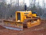
The problem is that I have been spoiled with the FEL on the Lindeman crawler.
The crawler weighs almost 6,000 pounds and has traction that is unquestionable.
It will go thru snow, mud and loose sand with out and problem.
The 1,500 pound tractor on rubber tires can't even compete with that.
So I said to myself: "Self, why are you carrying the bucket around all the time if you're never going to use it?"
So I took the loader off and sold it on ebay.
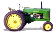
For those that would have liked to see what it looked with the loader on .. here are some photos.


I like it much better with out the loader if for no other reason than that you really couldn't see the tractor very well with the loader on.